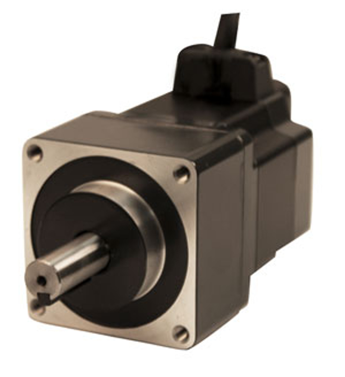
Product Description
- Specifications
- Product Options
- Tech Tips
- Announcements
- Documents
Product specifications for PK566AWR27LPS10
The PK566AWR27LPS10 specifies: This product has been discontinued, please contact your local sales office for more information.
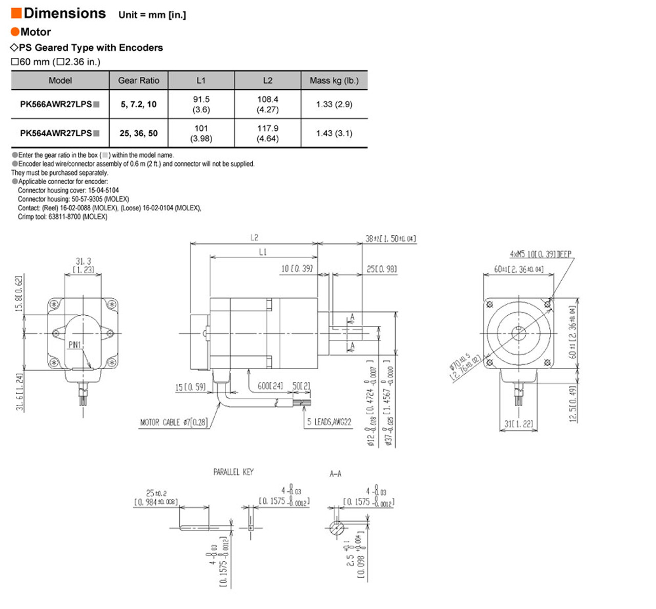
| Frame Size | - 2.36 in, 60 mm | |||||||||||||||||||||||||||||||||||||||||||||||||||||||||
| Motor Length | - 3.6 in., 91.5 mm | |||||||||||||||||||||||||||||||||||||||||||||||||||||||||
| Basic Step Angle | - 0.72º | |||||||||||||||||||||||||||||||||||||||||||||||||||||||||
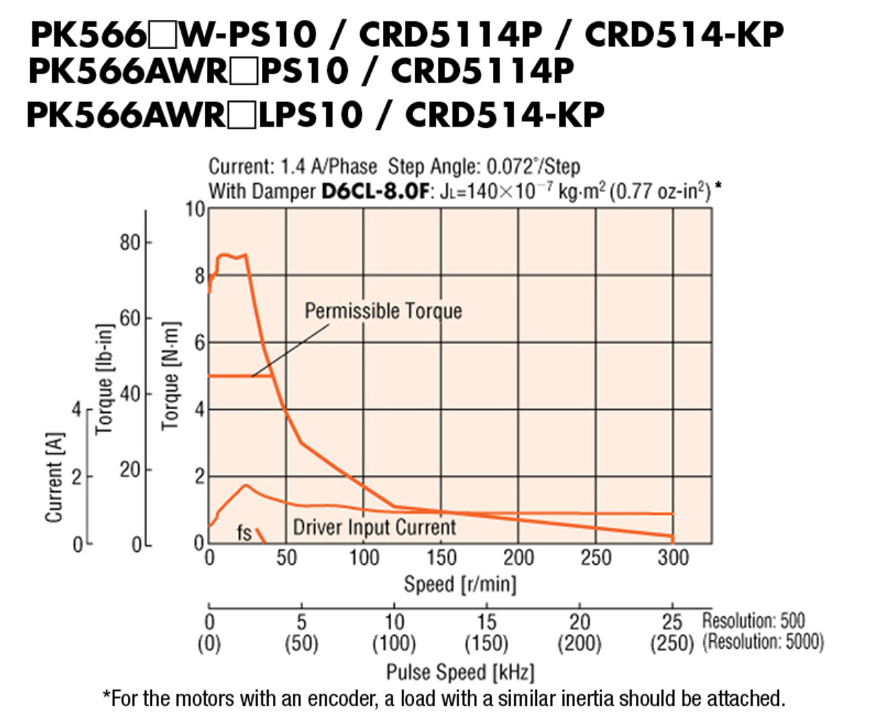
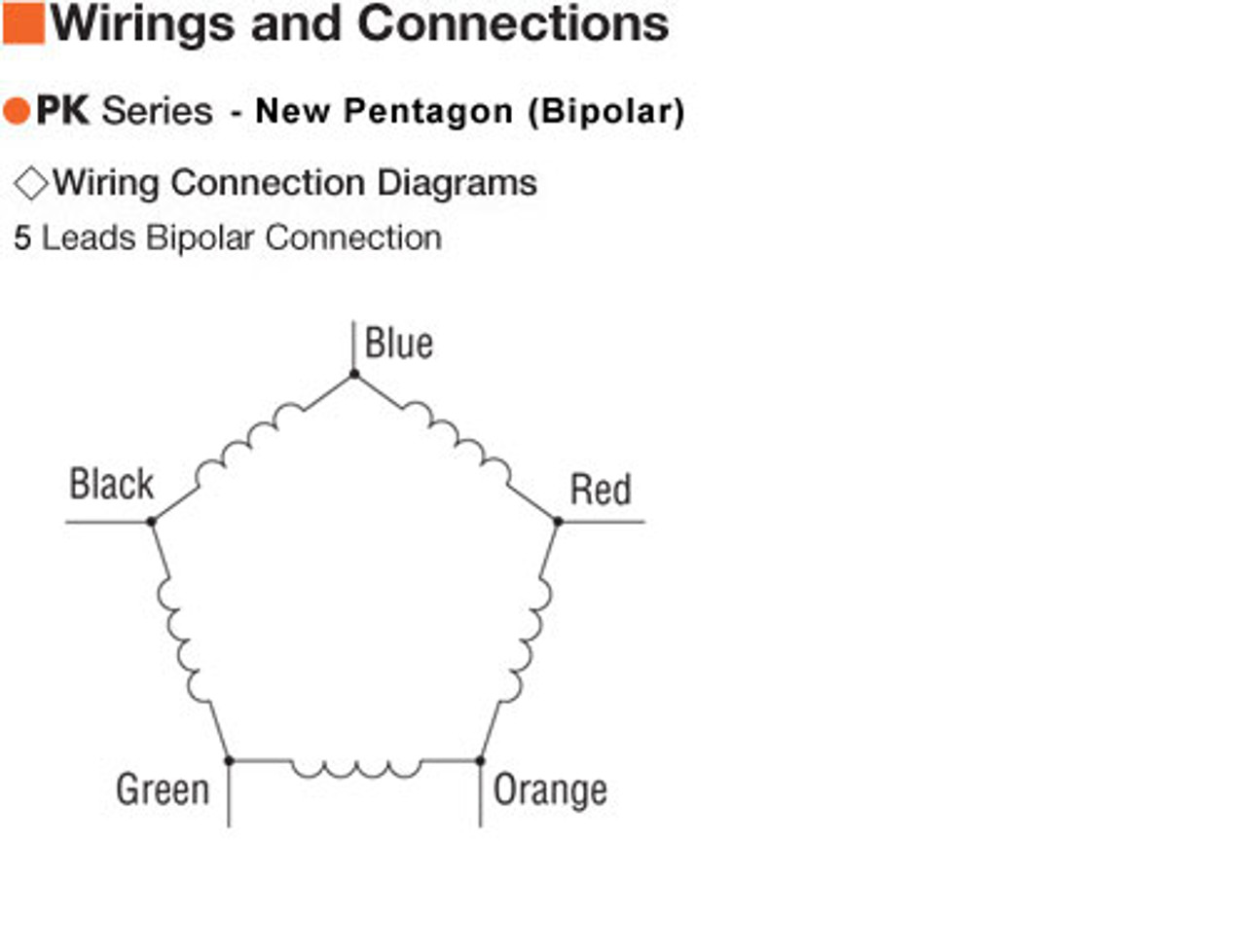
| Speed-Torque Characteristics | - Holding Torque Holding Torque | - 710 oz-in, 5 N·m | Current per Phase | - 1.4 A/phase | Type | - Geared | Shaft/Gear Type | - Planetary Gear | Gear Ratio (X:1) | - 10 :1 | Gear Type | - Planetary, Low Backlash (up to 35 arc min), Centered Shaft | Backlash | - 15 arc min (0.25º) | Motor Connection Type | - Flying Leads | Shaft | - Single | Step Angle | - 0.072 ° | Connection Type | - New Pentagon (Bipolar) | Lead Wires | - 5 | Rotor Inertia | - 1.53 oz-in², 280x10-7 kg·m² | RoHS Compliant | - Yes | Safety Standards | - EN, CE | Insulation Resistance | - 100 MΩ minimum under normal temperature and humidity, when measured by a 500 VDC megger between the windings and the motor casing. | Dielectric Strength | - Sufficient to withstand 1.5 kV, 50 Hz or 60 Hz applied for 1 minute between the windings and casing under normal temperature and humidity. | Temperature Rise | - Temperature rise of the coil measured by the Change Resistance Method is 176ºF (80ºC) or less (at rated current, at standstill, five phases energized). | Insulation Class | - [Motor] Class B [266ºF (130ºC)] | Ambient Temperature Range | - [Motor] 14ºF ~ 122ºF (-10ºC ~ 50ºC) (nonfreezing) | Ambient Humidity | - 85% or less (noncondensing) | Shaft Runout | - 0.002 in. (0.05 mm) T.I.R. at top of output shaft | Concentricity | - 0.003 in. (0.075 mm) T.I.R. | Perpendicularity | - 0.003 in. (0.075 mm) T.I.R. | Radial Play | - 0.001 in. (0.025 mm) max. of 1.12 lb. (5 N) | Axial Play | - 0.003 in. (0.075 mm) max. of 2.2 lb. (10 N) | Radial Load | - 0 in. from Shaft End = 56 lb, 0.2 in. from Shaft End = 60 lb, 0.39 in. from Shaft End = 67 lb, 0.59 in. from Shaft End = 76 lb, 0.79 in. from Shaft End = 87 lb, 0 mm from Shaft End = 250 N, 5 mm from Shaft End = 270 N, 10 mm from Shaft End = 300 N, 15 mm from Shaft End = 340 N, 20 mm from Shaft End = 390 N | Axial Load | - 22 lb, 100 N | |


